PSpice Voltage Sources:

VDC, VAC, VSIN, VPULSE, PWL

Models 

I need to use a triangle input waveform for my circuit, but I don't see one available in the Component list. How do I create one?

A triangle waveform, along with sawtooth, ramp, step, and impulse waveforms, can all be created through the Pulse capability of the Voltage Source component. The Pulse has seven parameters:

V1 - Initial voltage value
V2 - Pulsed voltage value
TD - Time delay value
TR - Rise time value
TF - Fall time value
PW - Pulse width value
PER - Period value

Triangle - For a triangle waveform, set V1 and V2 to the low and high voltages of the waveform. Set TD and PW to 0. TR and TF should be set to the rise and fall times of the triangle waveform. PER should be equal to TR + TF.

Sawtooth - For a sawtooth waveform, set V1 and V2 to the low and high voltages of the waveform. Set TD and PW to 0. TR should be set to the rise time of the sawtooth waveform. TF should be set to a small value in comparison to TR so that the falling transition is very quick but nonzero. PER should be equal to TR + TF.

Ramp - For a ramp waveform, set V1 and V2 to the initial and final voltages of the waveform. Set TD to 0. TR should be set to the simulation time that is to be used in transient analysis. Set PER to a value greater than the simulation time. The TF and PW values are not relevant to the ramp waveform.

Step - For a step waveform, set V1 and V2 to the initial and stepped voltages of the waveform. Set TD to the delay time before the step occurs. TR should be set to a small value in comparison to the simulation time so that there is a quick transition from V1 to V2. Set PW and PER to values greater than the simulation time so that the voltage stays at the V2 value for the rest of the simulation. The TF value is not relevant to the step waveform.

Impulse - For an impulse waveform, set V1 to 0. Set V2 to the impulse voltage. Set TD to the delay time before the impulse occurs. PW should be equal to 1/V2. TR and TF should be set to small values in comparison to PW so that the impulse has quick rise and fall transitions. PER should be greater than the simulation time so that the impulse only occurs once during the run.

If a current waveform is needed, the above information also applies to the Pulse capability of the Current Source component.

http://www.spectrum-soft.com/faq/help/faq163.shtm

A. Voltage Sources

i. VDC

  • This is your basic direct current voltage source that simulates a simple battery and allows you to specify the voltage value.

ii. VAC

  • A few things to note about the alternating current source, first PSpice takes it to be a sine source, so if you want to simulate a cosine wave you need to add (or subtract) a 90° phase shift. There are three values which PSpice will allow you to alter, these being:
    • ACMAG which is the RMS value of the voltage.
    • DC which is the DC offset voltage
    • ACPHASE which is the phase angle of the voltage
  • Note that the phase angle if left unspecified will be set by default to 0°

iii. VSIN

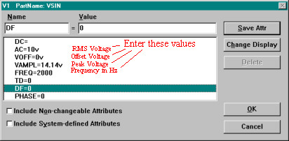
VSIN parameter window

  • The SIN type of source is actually a damped sine with time delay, phase shift and a DC offset. If you want to run a transient analysis you need to use the VSIN see how AC will effect your circuit over time. Do not use this type of source for a phasor or frequency sweep analysis, VAC would be appropriate for that.
    • DC the DC component of the sine wave
    • AC the AC value of the sine wave
    • Voff is the DC offset value. It should be set to zero if you need a pure sinusoid.
    • Vamplitude is the undamped amplitude of the sinusoid; i.e., the peak value measured from zero if there were no DC offset value.
    • FREQ is the frequency in Hz of the sinusoid.
    • TD is the time delay in seconds. Set this to zero for the normal sinusoid.
    • DF is the damping factor. Also set this to zero for the normal sinusoid.
    • PHASE is the phase advance in degrees. Set this to 90 if you need a cosine wave form.
  • Note that the normal usage of this source type is to set Voff, TD and DF to zero as this will give you a 'nice' sine wave.

iv. VPULSE

  • The VPULSE is often used for a transient simulation of a circuit where we want to make it act like a square wave source. It should never be used in a frequency response study because PSpice assumes it is in the time domain, and therefore your probe plot will give you inaccurate results.
    • DC the DC component of the wave.
    • AC the AC component of the wave.
    • V1 is the value when the pulse is not "on." So for a square wave, the value when the wave is 'low'. This can be zero or negative as required. For a pulsed current source, the units would be "amps" instead of "volts."
    • V2 is the value when the pulse is fully turned 'on'. This can also be zero or negative. (Obviously, V1 and V2 should not be equal.) Again, the units would be "amps" if this were a current pulse.
    • TD is the time delay. The default units are seconds. The time delay may be zero, but not negative.
    • TR is the rise time of the pulse. PSpice allows this value to be zero, but zero rise time may cause convergence problems in some transient analysis simulations. The default units are seconds.
    • TF is the fall time in seconds of the pulse.
    • TW is the pulse width. This is the time in seconds that the pulse is fully on.
    • PER is the period and is the total time in seconds of the pulse.
  • This is a very important source for us because we do a lot of work with the square wave on the wave generator to see how various components and circuits respond to it.

v. PWL (Piece-Wise Linear)

  • The PWL source is a Piece Wise Linear function that you can use to create a wave form consisting of straight line segments drawn by linear interpolation between points that you define. Since you can use as many points as you want, you can create a very complex wave form This source type can be a voltage source or a current source.
  • The syntax for this source type is flexible and has several optional parameters. The required parameters are two-dimensional points consisting of a time value and a voltage (or current) value. There can be many of these data pairs, but the time values must be in ascending order, and the intervals between time values need not be regular.
  • The two optional parameters are "DC" and "AC." The use of an AC parameter with this source is not very well documented and because this source is intended for use with a transient analysis any AC value would be ignored.

http://denethor.wlu.ca/PSpice/pspice_tutorial.html


Transient analysis of square wave using PSPICE

Asked 2 years ago
Active 2 years ago
Viewed 3k times
0

I need to do a transient analysis of my BJT cascode amplifier. I was asked to use VPULSE as the source. I need to set VPULSE for +-10mV, 50% duty cycle square wave at 128 kHz with rise time and fall time of 10 ns. 

In PSPICE, I had set the VPULSE's attribute as

  V1=-0.01
V2 = 0.01
TR = 10ns
TF = 10ns
PW = 3.90625u
PER = 7.8125u

The transient analysis setting is

 Print Step = 10ns
Final time = 9us
No print delay = 100ns

I would like to know how can I set my 50% duty cycle and is my analysis setting correct?

enter image description here

My simulation result shown above.

pspice transient
share improve this question
edited Oct 3 '18 at 14:35
asked Oct 3 '18 at 14:10
sterstar
2522 silver badges77 bronze badges
  • Thanks. How can I set 50% of duty cycle? – sterstar Oct 3 '18 at 14:28
  • You can't "set" it, you have to calculate all the values by hand. I converted my comment into an answer BTW. That plot is not the output of the vpulse source so not relevant here. Also, the error you made is very small, you cannot see that 10ns error you made in such a plot. Your duty cycle is 50.128% and that's so close to 50% that it is hard to see in a plot. – Bimpelrekkie Oct 3 '18 at 14:29

  • my bad. I had changed the picture – sterstar Oct 3 '18 at 14:35
add a comment

2 Answers

0

What I do:

128 kHz = 7.8125us so your PER is correct.

Then I make PW = PER/2 but subtract half of the the total of the transition times: TR + TF = 20 ns => half of that = 10 ns.

So PW = 3.90625 us - 10 ns = 3.89625 us.

So make PW = 3.89625u and then you would have 128 kHz with a perfect 50% duty cycle.

share improve this answer
answered Oct 3 '18 at 14:29
Bimpelrekkie
69.2k22 gold badges7575 silver badges155155 bronze badges
add a comment
-1

Well, your pulse width is not quite right for a square wave, but it is close. If you want a square wave you have to account for the rise/fall times, so

PW=PER2−TR

assuming that TR and TF

are equal, and where the variable names are the names used by SPICE (all caps, no subscripts).

Note that some simulators will require that you set the maximum timestep equal to the TF/TR

if you really want those rise/fall times.

https://electronics.stackexchange.com/questions/399174/transient-analysis-of-square-wave-using-pspice